


Diskreter ADC-Bausatz
Diskreter ADC-Bausatz
This kit teaches you how analog-to-digital conversion actually works — built from discrete comparators, flip-flops, and logic gates instead of a black-box ADC chip. You get the board, every component, and a 37-page engineering design guide.
Skills you'll build
Verfügbarkeit für Abholungen konnte nicht geladen werden


Skills you'll build
What's included
- Leiterplatte
- Alle elektronischen Komponenten — LM393N, 74HC74N, 74HC32N und alle zugehörigen Teile
- Potentiometer — analoge Eingangssteuerung
- 8 × LEDs — binäre Ausgangsanzeige
- Dokumentation — Montageanleitung und ADC-Theorie
About this kit
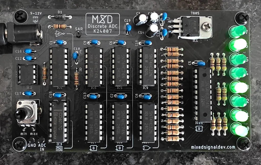
Haben Sie sich jemals gefragt, wie analoge Signale digital werden? Mit dem Discrete ADC DIY Kit bauen Sie Ihren eigenen 8-Bit-Analog-Digital-Wandler von Grund auf neu – unter Verwendung echter diskreter Logikkomponenten anstelle eines einzelnen integrierten ADC-Chips. Stellen Sie den analogen Eingang mit einem Potentiometer ein und beobachten Sie, wie das Ergebnis live über 8 LEDs als 8-Bit-Binärwert angezeigt wird.
Die Schaltung verwendet einen LM393N Dual-Komparator, einen 74HC74N Dual-D-Flip-Flop, ein 74HC32N Quad-OR-Gatter und unterstützende Logik zur Durchführung der Umwandlung – dieselben fundamentalen Operationen, die in jedem ADC-IC verborgen sind, werden sichtbar und verständlich gemacht.
Alle Komponenten sind durchsteckbar (Through-Hole), wodurch dieses Kit für jeden zugänglich ist, der mit grundlegenden Lötkenntnissen vertraut ist.
What you'll learn
- Wie die Analog-Digital-Wandlung auf Schaltungsebene funktioniert – nicht innerhalb eines Black-Box-ICs
- Wie eine Komparatorschaltung (LM393N) eine Spannung mit einem Referenzschwellenwert vergleicht
- Wie D-Flip-Flops (74HC74N) digitale Zustände speichern und durch aufeinanderfolgende Umwandlungsstufen weitergeben
- Wie OR-Gatter (74HC32N) Logiksignale in der ADC-Wandlungskette kombinieren
- Wie man eine 8-Bit-Binärausgabe von LEDs abliest
- Wie diskrete Logik-ICs kombiniert werden, um die gleiche Funktion auszuführen, die in jedem ADC-Chip verborgen ist
- Wie das Drehen eines Potentiometers den analogen Eingang ändert und die binäre LED-Ausgabe in Echtzeit verschiebt
Prerequisites & difficulty
Technical specifications
FAQ
Was ist ein ADC und warum sollte man ihn aus diskreten Bauteilen bauen?
Ein ADC wandelt eine analoge Spannung in eine digitale Binärzahl um. Wenn Sie einen aus diskreten Bauteilen aufbauen, können Sie jede Stufe der Umwandlung sehen – den gleichen Prozess, der in jedem ADC-IC verborgen ist, wird sichtbar gemacht.
Welche Binärkenntnisse benötige ich?
Sie müssen Binärzahlen verstehen – was jedes Bit darstellt und wie man einen 8-Bit-Wert liest. Wenn Sie binär bis 255 zählen können, sind Sie bereit.
Ist dies für Anfänger geeignet?
Mittelstufe. Grundlegende Erfahrung im Durchstecklöten ist erforderlich. Wenn Sie neu im Löten sind, beginnen Sie zuerst mit dem Löt-Übungskit oder dem BCD-Zähler.
Browse the documentation
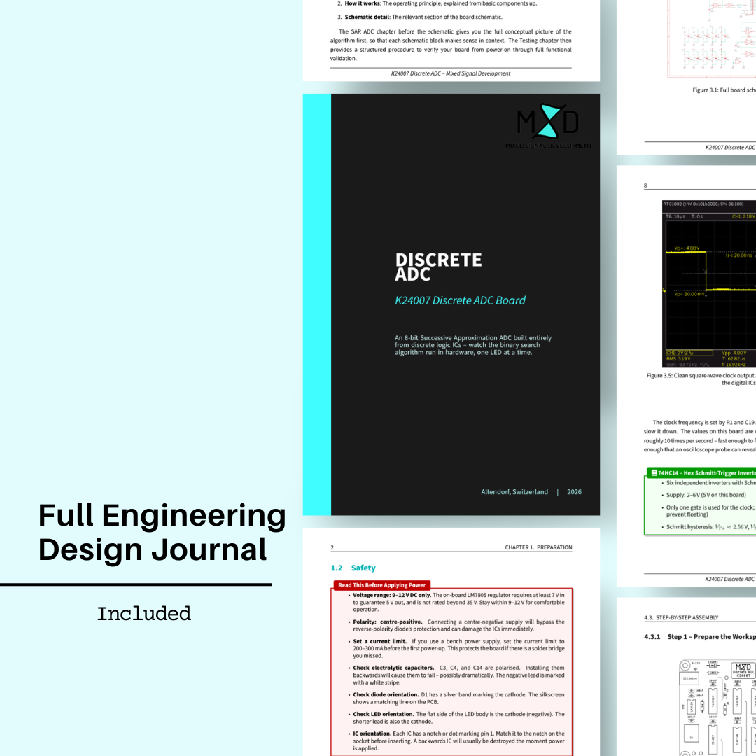
Every kit includes a full engineering design guide. Here's a preview.
Our approach
Want to see how our documentation is different?
Every MSD kit ships with an engineering design guide written by the person who designed the board. Not a pinout diagram — a real document.
Premium Engineering Files
Thank you for your purchase. Your files are ready to download.