


Discrete Class D Amplifier DIY Kit
Discrete Class D Amplifier DIY Kit
Verfügbarkeit für Abholungen konnte nicht geladen werden


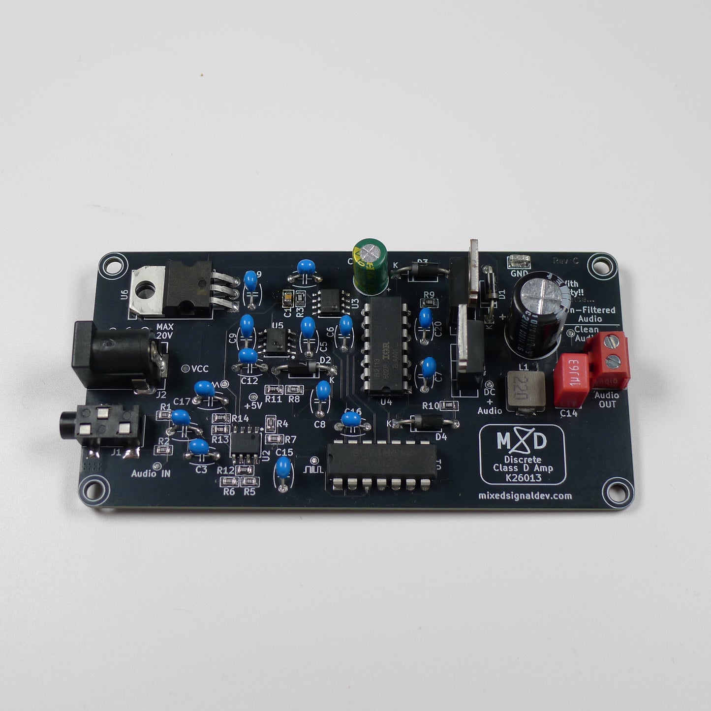
Build a real Class D power amplifier from a 555, a comparator and two MOSFETs — no amplifier chip, with every stage of the signal chain visible on a scope.
Skills you'll build
What's included
- PCB — high-quality printed circuit board
- All components — 555 ×2, LM393, 74HC14, IR2113, IRLZ44N ×2, L7805, 22 µH inductor & passives
- Full documentation — assembly, theory & troubleshooting guide
- Printable Assembly Print sheet
About this kit
The Discrete Class D Amplifier DIY Kit is a complete, working audio power amplifier you build from fundamental building blocks — with no dedicated amplifier chip anywhere on the board. A 555 timer generates a ~188 kHz carrier, an LM393 comparator turns your audio into pulse-width-modulated pulses, an IR2113 gate driver and a pair of IRLZ44N MOSFETs switch the power, and a simple LC filter reconstructs it all back into clean, amplified sound.
Feed it any 3.5 mm audio source, power it from a 12–20 V supply, connect a 4 Ω or 8 Ω speaker, and hear a Class D amplifier whose every stage you can point to. Labelled test points at each node turn the board into a live map of the signal chain — ideal for probing with an oscilloscope.
This is an intermediate-level kit combining through-hole (THD) and surface-mount (0805) components — a great project to practise both techniques on a single board.
📚 Prerequisites
You'll need some previous knowledge to get the most out of this kit:
► Ohm's Law and basic voltage-divider intuition
► A feel for how capacitors charge and block DC
► Some experience with SMD passives (0805) recommended — the through-hole parts are beginner-friendly
✨ Key Features
What you'll learn
- Pulse-width modulation (PWM) and how a comparator plus a triangle carrier creates it
- Biasing an audio signal to mid-rail for single-supply operation
- Half-bridge switching and the high-side gate-drive (bootstrap) problem
- Why a Class D amplifier is so efficient, and how an LC filter reconstructs the audio
- Switch-mode PCB layout: tight switching loops, short gate traces and solid grounding
- A self-standby circuit that detects silence, built from a comparator and a second 555
Prerequisites & difficulty
Technical specifications
FAQ
Do I need an oscilloscope to build this kit?
No — a multimeter is enough to assemble, power up and verify the board. An oscilloscope is optional, but it lets you watch the 188 kHz carrier, the PWM and the switching node, turning the kit into a full switch-mode lab.
What can I power it with?
Any DC supply from 12 to 20 V through the barrel jack. A current-limited bench supply is ideal for the first power-up. Never exceed 20 V — the limit is set by the IR2113 gate driver.
Is it mono or stereo?
The amplifier is mono: the left and right channels of your 3.5 mm source are summed into a single channel.
What speaker should I use?
A 4 Ω or 8 Ω speaker. Output power scales with supply voltage and lower impedance, always within the components' ratings.
Is this kit suitable for a beginner?
It is an intermediate kit. If you have soldered 0805 SMD passives before you'll be comfortable; the through-hole parts are beginner-friendly. Complete beginners should start with the Soldering Practice Kit first.
Browse the documentation
Every kit includes a full engineering design guide. Here's a preview.
Our approach
Want to see how our documentation is different?
Every MSD kit ships with an engineering design guide written by the person who designed the board. Not a pinout diagram — a real document.
Premium Engineering Files
Gerbers, firmware and simulation files come with every kit. After you order, enter your order email here to download them.